Hack your phone: turn your volume buttons into GPIO ports
This post was originally published on Engineering@TelenorDigital.
As described in Firefox OS as an IoT platform, we are re-using existing phone hardware to build Gonzo, our wireless camera. While this has some major benefits, like more mature software and a cheaper pricepoint, it also has a major downside: because a phone motherboard is not meant to be an IoT board it doesn’t offer any extensibility points.
A standard IoT dev board like the Raspberry Pi or Arduino comes with a number of General Purpose Input/Output (GPIO) pins. As a hardware developer you can use these pins to add new functionality to your board. For example, you can add new sensors to the board. For Gonzo we ran into the issue that we would like to add a LED light to the device, but the phone mainboard we use does not have GPIO ports.
But we’re creative thinkers, so time for a hardware hack! Let’s re-map the volume buttons of your phone into generic GPIO ports.
Re-mapping in the kernel
Most phones have a number of GPIO ports available, but they are not mapped to be generic GPIO. For instance, the volume buttons are mapped as input devices. If you have access to the Linux kernel of your Android/Firefox OS phone you can find the mappings, and change that. Find the board-XXXX.c file (or board-XXXX-io.c) in the Linux kernel, and search for gpio. On the GeeksPhone Keon it’s quite easy to find the volume mappings. There is the reference to the GPIO ports, and then in the kernel they’re mapped to a keymap. Essentially the volume buttons are a two button keyboard.
static unsigned int kp_row_gpios[] = {31, 32};
static unsigned int kp_col_gpios[] = {36};

static const unsigned short keymap[ARRAY_SIZE(kp_col_gpios) *
                                   ARRAY_SIZE(kp_row_gpios)] = {
  [KP_INDEX(0, 0)] = KEY_VOLUMEDOWN,
  [KP_INDEX(0, 1)] = KEY_VOLUMEUP,
};
From here we can also see that to implement this keymap there are three GPIO pins used: 31, 32 and 36. We can now comment out the keymap declaration and add a simple device driver that maps the GPIO ports to be generic ports instead:
} gonzo_gpio_map[] = {
  { BLUE_LED, 31, "blue_led", 1, 0, 0 },
  { GREEN_LED, 32, "green_led", 1, 0, 0 },
  { RED_LED, 36, "red_led", 1, 0, 0 },
};
The device driver is nothing more than a thin wrapper around linux/gpio.h that exposes itself through a file descriptor. Because we named the module ‘gonzo-sysfs’ when declaring the device:
static struct platform_device gonzo_sysfs = {
  .name = "gonzo-sysfs",
  .id = -1,
};
the ports will be exposed as file descriptors under /sys/devices/platform/gonzo-sysfs. Recompile the kernel and push it to the device (or if you have a Keon grab a pre-made build).
Re-mapping on hardware
Now that we have exposed the ports through the kernel we need to find out how the ports are laid out on the mainboard. As phone manufacturers don’t give out spec sheets this is some manual labour. If we strip off the volume button sticker from the buttons we are presented with the following:
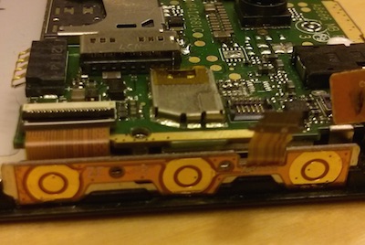
From left to right: volume down, volume up, power
This connects to the mainboard via a simple connector (red) which plugs into the green socket.
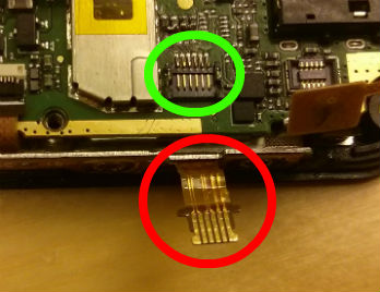
Every button consists of two rings. Each of these rings need to mapped to the mainboard, which has 6 lanes to communicate. We need to figure out which ring connects to which lane. For this we can use a normal multimeter, set it to sound mode and connect the ring to all lanes.

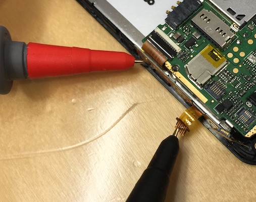
From this information we find:
- Volume down, inner ring = lane 1
- Volume down, outer ring = lane 2
- Volume up, inner ring = lane 3
- Volume up, outer ring = lane 2
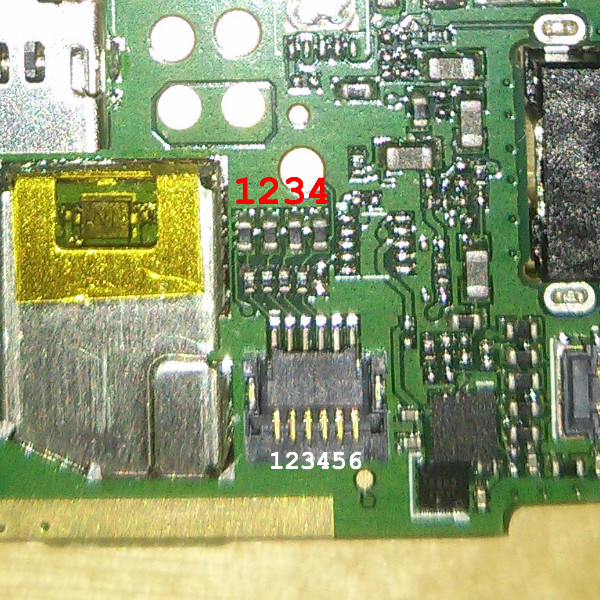
This makes sense, given that we found in the kernel that we use three pins to create the volume keyboard. In total we have six lanes though, of which four run to a diode. 1-3 for the volume buttons, 4 for power, and 5 and 6 for ground. Again, quite easy to check with a multimeter.
Adding a LED
In the kernel the GPIO pins were mapped as 31, 32 and 36. How these IDs map to the diodes depends on the phone, you cannot assume that 1=31, 2=32, etc. Testing is quite simple, just toggle the GPIO switch from the kernel, and measure the current that goes through the diode.
While testing we found out that we could not reliable use diode 1, as it would also turn on diode 3. Diodes two and three are fine, and they are mapped to 2=32 and 3=36. Start by soldering some soldering wire to one of these diodes, and solder some other soldering wire to ground. In a LED circuit we also need to attach a resistor between the diode and the LED. Here you see the green wire with a resistor, and the white wire from ground. Ready to attach a LED.
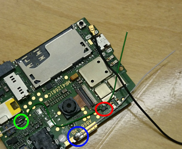
Green: soldering wire attached to diode 3. Blue: soldering wire attached to ground. Red: resistor.
We can now add the LED to the green and white soldering wire, closing the circuit.
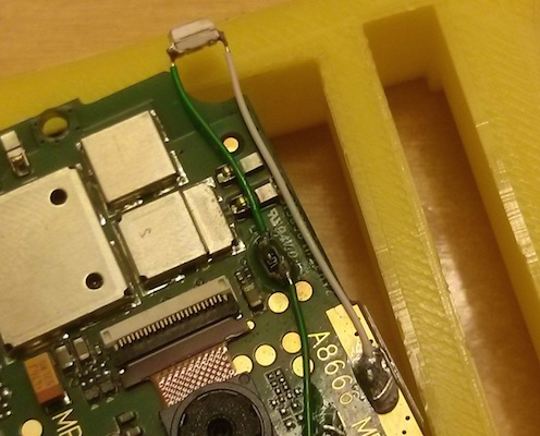
Controlling the LED
As we mapped the diode with ID 36 to red_led in the kernel, earlier in this article, we now have a file descriptor that we can use to control the LED light. After connecting to the device via adb shell, we can control the LED as follows:
# enable
echo 1 > /sys/devices/platform/gonzo-sysfs/red_led

# disable
echo 0 > /sys/devices/platform/gonzo-sysfs/red_led

# get status
cat /sys/devices/platform/gonzo-sysfs/red_led
Wrapping up
As we disconnected the buttons, there is no way to put on the device. To keep the power button working, either reconnect the buttons again (only power will work), or solder a simple push button to diode 4.
This is how Gonzo looks like with it’s new red LED attached:
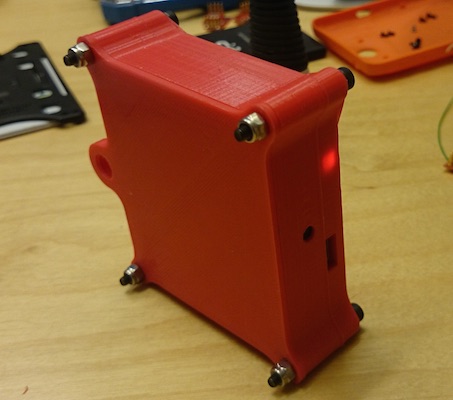
Conclusion
Although your mobile phone board does not ship with easy to reach GPIO pins, it’s quite feasible to re-use some of the existing pins that are currently mapped to something else. In general there are also a bunch of pins around the touch panel and the screen. When you rip out the mainboard these pins are up for grabs. Dive into the kernel, find where they are mapped, and use a multimeter and some electronics 101 to see how to re-map the pins!
Kernel changes for the Keon are on GitHub, or get a pre-made build.