Porting I2C code from Arduino to Atmel ASF
This post was originally published on Engineering@TelenorDigital.
I’m in the middle of writing the software for our very first LoRa device, and the module we used as a basis is based around an Atmel SAM D20 MCU. Which means writing code against Atmel Software Framework (ASF). I figured that porting the code to read a sensor over I2C to ASF would be very straight forward, but it took me 2 days. So for my future self: here’s how to read data from the MPU-6050 over I2C in ASF.
Arduino
The Arduino code is pretty clear. It uses the Wire.h library, sends a wakeup command, and then you can start reading data.
#include <Wire.h>
const int MPU_addr = 0x68; // I2C address of the MPU-6050

void setup() {
  Wire.begin();
  Wire.beginTransmission(MPU_addr);
  Wire.write(0x6B); // PWR_MGMT_1 register
  Wire.write(0); // set to zero (wakes up the MPU-6050)
  Wire.endTransmission(true);
  Serial.begin(9600);
}

void loop() {
  Wire.beginTransmission(MPU_addr);
  Wire.write(0x3B); // starting with register 0x3B (ACCEL_XOUT_H)
  Wire.endTransmission(false);
  Wire.requestFrom(MPU_addr, 14, true); // request a total of 14 registers

  int16_t AcX, AcY, AcZ, Tmp, GyX, GyY, GyZ;

  AcX = Wire.read() << 8 | Wire.read(); // 0x3B (ACCEL_XOUT_H) & 0x3C (ACCEL_XOUT_L)
  AcY = Wire.read() << 8 | Wire.read(); // 0x3D (ACCEL_YOUT_H) & 0x3E (ACCEL_YOUT_L)
  AcZ = Wire.read() << 8 | Wire.read(); // 0x3F (ACCEL_ZOUT_H) & 0x40 (ACCEL_ZOUT_L)
  Tmp = Wire.read() << 8 | Wire.read(); // 0x41 (TEMP_OUT_H) & 0x42 (TEMP_OUT_L)
  GyX = Wire.read() << 8 | Wire.read(); // 0x43 (GYRO_XOUT_H) & 0x44 (GYRO_XOUT_L)
  GyY = Wire.read() << 8 | Wire.read(); // 0x45 (GYRO_YOUT_H) & 0x46 (GYRO_YOUT_L)
  GyZ = Wire.read() << 8 | Wire.read(); // 0x47 (GYRO_ZOUT_H) & 0x48 (GYRO_ZOUT_L)
}
Now, let’s port it…
ASF
First things first, let’s set up the I2C bus. Atmel uses something called SERCOM as their serial communication interface. I think on my module there are six or something, so look in the datasheet of your module to see which SERCOM bus is configured for I2C (in my datasheet it was listed in the pinout).
#define ADDRESS     0x68   // I2C address of the sensor

struct i2c_master_module module;

struct i2c_master_config config;
i2c_master_get_config_defaults(&config);

// HERE: specify which SERCOM
enum status_code initStatus = i2c_master_init(&module, SERCOM2, &config);
i2c_master_enable(&module);

// check the status_code here, etc.
Please note that ADDRESS can also be 0x69, if AD0 is high.
Resistors
When doing I2C normally you need two pull up resistors on SCL and SDA. Verify whether your board / dev kit already has these resistors in place, otherwise adding them as well on your breadboard will probably throw an error.
Powering up the sensor
To start communicating with the sensor we need to power it up. If you look at the Arduino code it looks like it is sending two packets, but this is actually wrong (and it took me quite some time to find this out). It’s one package with 2 bytes.
uint8_t maxRetries = 64;

enum status_code powerOnStatus;
// POWER ON THE SENSOR!
{
    uint8_t retryCount = 0;

    static uint8_t buffer[2] = { 0x6b, 0x0 }; // power on packet
    struct i2c_master_packet packet = {
        .address = ADDRESS,
        .data = buffer,
        .data_length = 2,
    };

    while ((powerOnStatus = i2c_master_write_packet_wait(&module, &packet)) != STATUS_OK)
    {
        if (++retryCount >= maxRetries) break;
    }
}
Now here comes a stupid thing. When I was doing this, at some point my status code when writing was STATUS_ERR_BAD_ADDRESS. This was because I had VCC to 3.3V, not to 5V! Light on the module was still on, but it didn’t work. So check that you have 5V input.
Who am I
Now check whether we can read registers from the sensor. There’s a ‘who am I’ register that will return 0x68.
uint8_t whoAmI;
{
    uint8_t retryCount = 0;

    static uint8_t buffer[1] = { 0x75 }; // who am I
    struct i2c_master_packet packet = {
        .address = ADDRESS,
        .data = buffer,
        .data_length = 1,
    };

    // here use the no_stop variant
    while (i2c_master_write_packet_wait_no_stop(&module, &packet) != STATUS_OK)
    {
        if (++retryCount >= maxRetries) break;
    }

    // and here it sends stop automatically
    UNUSED(i2c_master_read_packet_wait(&module, &packet));
    whoAmI = buffer[0];
}

// check that whoAmI == 0x68
Reading data
Now that we set this thing up we can start reading some data. First give it some time to boot up and then start reading.
// give the sensor 50 ms. to gather some data
delay_ms(50);

// send 1 byte with the offset we want to read
static uint8_t writeBuffer[1] = { 0x3b }; // ACCEL_XOUT_H location
struct i2c_master_packet writePacket = {
    .address = ADDRESS,
    .data = writeBuffer,
    .data_length = 1,
};

i2c_master_write_packet_wait_no_stop(&module, &writePacket);

// now do the actual reading
static uint8_t buffer[14];
struct i2c_master_packet readPacket = {
    .address = ADDRESS,
    .data = buffer,
    .data_length = 14,
};
enum status_code s4 = i2c_master_read_packet_wait(&module, &readPacket);

int counter = 0;

int16_t acX = buffer[counter++] << 8 | buffer[counter++]; // 0x3B (ACCEL_XOUT_H) & 0x3C (ACCEL_XOUT_L)
int16_t acY = buffer[counter++] << 8 | buffer[counter++]; // 0x3D (ACCEL_YOUT_H) & 0x3E (ACCEL_YOUT_L)
int16_t acZ = buffer[counter++] << 8 | buffer[counter++]; // 0x3F (ACCEL_ZOUT_H) & 0x40 (ACCEL_ZOUT_L)
int16_t tmp = buffer[counter++] << 8 | buffer[counter++]; // 0x41 (TEMP_OUT_H) & 0x42 (TEMP_OUT_L)
int16_t gyX = buffer[counter++] << 8 | buffer[counter++]; // 0x43 (GYRO_XOUT_H) & 0x44 (GYRO_XOUT_L)
int16_t gyY = buffer[counter++] << 8 | buffer[counter++]; // 0x45 (GYRO_YOUT_H) & 0x46 (GYRO_YOUT_L)
int16_t gyZ = buffer[counter++] << 8 | buffer[counter++]; // 0x47 (GYRO_ZOUT_H) & 0x48 (GYRO_ZOUT_L)

// send the data off
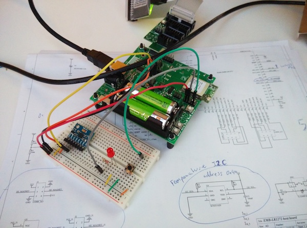
And that’s it. Data now flows in and we can start consuming it. Here’s a nice photo of the sensor on a breadboard.
